If a fault is not able to be cleared, the alternative supply path around the ring is connected and power is subsequently restored. This can cause serious operational issues where even a small interruption results in wasted product or processing sequences to be reset.
Many networks can be operated in a closed ring arrangement as long as protection grading and fault levels are properly considered. It is not generally possible to operate a system as a closed ring using overcurrent standard grading methods while achieving discrimination and maintaining reasonable tripping times.
Without suitable discrimination, nuisance tripping of upstream feeders may occur and fault location be difficult to determine. If reasonable tripping times are not maintained, potential fault energy levels will significantly rise and increase risk to both personnel and equipment. To maintain both suitable tripping times and overcurrent grading for faults along a ring there are common two methods of protection that may be used in a closed ring system; differential protection and blocking.
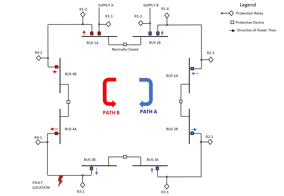
 Figure 1: Example of a closed ring network experiencing a fault using both methods of protection.
Blocking
Blocking uses directional sensing of a fault and communication to upstream protection relays. With this method, each individual relay’s overcurrent protection settings would normally not appear to grade with the upstream relay.
The use of directional sensing identifies if the fault is downstream of the protection relay and sends a blocking command to all feeders upstream of itself on the ring in order to give the closest relay time to trip before any others. To use this method a small delay is included in all trips to allow for the detection of a blocking signal from any downstream protection relays.

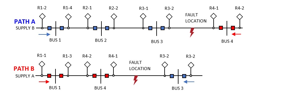
During the above fault there are 2 parallel supplies, Path A and Path B. Path A supply to the fault will be seen by all the protection relays in BLUE above, but only R3-2 will trip on this fault event. This relay senses the direction of the fault, and communicates to R3-1, R2-2, R2-1, R1-4 and R1-2 to block their trip functions in order to be the only protection relay to activate on this path. Path B is seen by all the protection relays in RED above, but only R4-1 will trip on this fault event.
This relay senses the direction of the fault, and communicates to R4-2, R1-3 and R1-1 to block their trip functions in order to be the only protection relay to activate on this path.
With a small number of upstream devices from the furthest fault location, blocking can be an effective method of applying protection to a closed ring. As this number increases with the size of the ring, additional blocking to upstream protection relays must be added, increasing complexity of the system.
Differential
Differential protection allows for sensitive, fast acting detection of a fault between two feeders or across a bus. Bus differential protection can be achieved via high or low impedance differential and is dependent on relay and current transformer configuration.

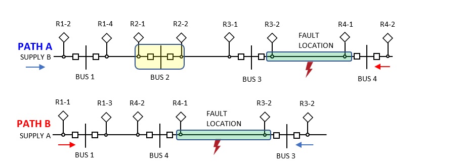
During the same fault conditions that were previously considered, differential protection will detect and respond to this fault by operating both protection relays R4-1 and R3-2. These relays must communicate with each other to compare the currents seen by each relay, to ensure these values are equal to each other. If there is a sudden change in current in the green region that is only seen by one of the relays, this will indicate that there is a fault in this zone, and both relays will trip. This protection has a very fast response time and can be used to individually protect specific zones in the ring.
Each bus zone can also be protected using the same method. In the region highlighted yellow, Bus 2 is protected by relays R2-1 and R2-2. If there are additional feeders on a bus these must also be included in the bus protection. As the number of feeders increases on a bus, this increases in cost and complexity.
This individual element protection is repeated for all zones in the system, for operation as a closed ring configuration. Any fault is detected by the local protection relays in the zone and trips are cleared quickly using this method. Differential protection allows for grading of upstream feeders as each feeder only needs to consider its own zone and the primary ring supply feeder.
Both of these protection methods allow for fast protection trips while maintaining grading within the system. Each method has different benefits depending on the number of buses and feeders on each bus.
Teck Global
The team at Teck Global has implemented both of these methods for different sites across regional Western Australia and are experienced with HV reticulation systems of all sizes and voltages. For any further information on protection systems, whether it be reticulation, grading, relay configuration or HV submissions, contact the team at Teck Global today to see how they can assist you.
