
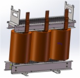
The Iron core and windings play a key role in defining the characteristics of a transformer. There are a number of different transformer shapes available. Circular, oblong (oval) and rectangular shapes are the most commonly used. In this post we will investigate the difference between these shapes, and which shape offers the most benefits.
Iron core shape
The diagram shows the three different core shapes available: circular, oblong and rectangular:
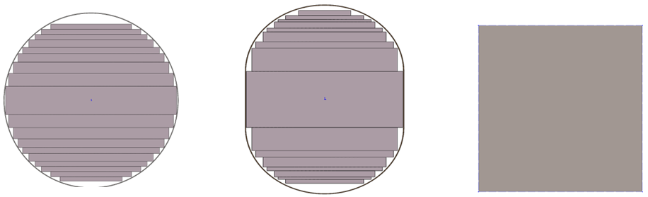
The circular shaped core doesn’t completely fill the air gap within the winding with magnetic flux carrying steel. This is due to the limitations of cutting and stacking the CRGO laminations efficiently. Similarly, the oblong iron core has air gaps as well. However the rectangular shaped core is easy to produce and the winding can easily be made to fit this shape. The air gap produces inefficiencies and as a result, the rectangular iron core has the best no-load loss performance.
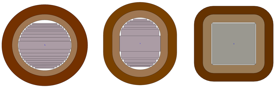
The image below shows the air gaps when covered by the LV and HV windings. White is the gap between the core and the windings.
Radial Forces
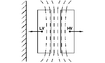
The produced radial force is a resultant vector from the leakage flux and is mostly in the axial direction (except in the ends of the windings). The maximum radial force occurs half way up coils as seen in the figure below. Radial forces act outwards on the outer winding and inwards on the inner winding.
Comparison of resistance to short circuit
Radial forces act on a transformer winding around the central axis. The maximum force experienced by a transformer occurs during short circuit events. In such an event the round winding maintains its circular shape as the forces are even throughout coil.
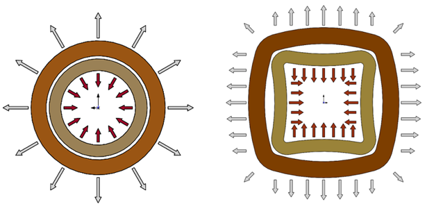
However a rectangular winding experiences forces unevenly around the coil, stronger in the middle and weaker at the edges. This can lead to a physical distortion in the winding potentially leading to permanent and potentially catastrophic damage. tends to become a more rounded configuration, because of the radial forces generated under the short circuit condition.
The forces generated in a transformer which has been subject to short circuit conditions, are more magnified compared to those under normal operating conditions. This is due to the large currents produced by the short circuit. These radial forces cause the inner winding of the transformer to be crushed inwardly against the core, and the outer winding to be expanded outwardly (in opposition to the inner winding).
Under the short circuit, the rectangular coil design transformer will undergo substantial geometry changes in the coil shape leading to coil/insulation damage because it wants to become circular. The impedance change is up to 7.5%.
Which is the most beneficial shape?
The figure below attempts to condense the information into a small table.
| Transformer Shape Comparison | Short Circuit Handling | No Loud Loss Performance | Price |
|---|---|---|---|
| Round | Best | Poor | Highest |
| Oblong | Better | Better | Middle |
| Square | Poor | Best | Cheapest |
As per the chart table larger transformers and transformers used in heavy industry Round is clearly the preferred core shape for transformers. Longevity below, it’s clear that the circular and oblong transformer are the best option. However for domestic and commercial supply and where cost is a driving factor square cores can come out ahead.
To find out more information please contact the team at Teck Global, do discuss the best option for your needs.